Home » Without Label » Timer And Contactor R Relay Diagram - Timer And Contactor R Relay Diagram : Https Www ... - When designing circuits using time delay relays, questions such as what initiates a time delay relay, does the timing start with the application or release of voltage, when is the output relay energized, etc., must be asked.
Timer And Contactor R Relay Diagram - Timer And Contactor R Relay Diagram : Https Www ... - When designing circuits using time delay relays, questions such as what initiates a time delay relay, does the timing start with the application or release of voltage, when is the output relay energized, etc., must be asked.
Timer And Contactor R Relay Diagram - Timer And Contactor R Relay Diagram : Https Www ... - When designing circuits using time delay relays, questions such as what initiates a time delay relay, does the timing start with the application or release of voltage, when is the output relay energized, etc., must be asked.. First we understand what is no and nc point. Timer and contactor wiring diagram pdf. It is an electrical component used in a circuit with a lower voltage or a smaller current to switch on or off a circuit with a higher voltage and larger current. Starter contactor aka starter relay is an intermittent duty relay meaning it is designed to be turned on only for short periods of time. Hager contactor wiring diagram single phase 1 with overload and.
Engineering electrical diagram contactor and timer. Operationally, it works the same way. When designing circuits using time delay relays, questions such as what initiates a time delay relay, does the timing start with the application or release of voltage, when is the output relay energized, etc., must be asked. Overload relays may be set for 2 different operational modes—manual reset only or. Electronic timers, reversing contactor modules, and more.
Timer And Contactor R Relay Diagram - Timers that have ... from lh5.googleusercontent.com Time delay relays are simply control relays with a time delay built in. Engineering electrical diagram contactor and timer. Overload relays may be set for 2 different operational modes—manual reset only or. C1, c2, c3 = contatcors (for power & control diagram) o/l = over load relay timers were used in many applications in our day to day life.one can see the timers in washing machines,micro ovens etc. Contactor switching time is higher than relay. 2 electrical relay diagram symbols. The compact size of these relays makes them ideal for downsizing equipment. A wiring diagram is a streamlined conventional photographic representation of an electric circuit.
Time relay refers to a kind of relay whose output circuit needs to make an obvious change (or contact action) after adding (or removing) the input action signal in a specified and accurate time.
Relay logic is a method of operating industrial electrical circuits with the help of relay and contacts. Timer and contactor r relay diagram : Ladder diagram or electrical schematic or elementary diagram can be divided into two. Engineering electrical diagram contactor and timer. Timer and contactor r relay diagram : Using an adapter plate, you can also mount it for standalone use. Starter contactor aka starter relay is an intermittent duty relay meaning it is designed to be turned on only for short periods of time. Time delay after coil normally open normally closed normally open normally closed relay, etc. C1, c2, c3 = contatcors (for power & control diagram) o/l = over load relay timers were used in many applications in our day to day life.one can see the timers in washing machines,micro ovens etc. 6 adjustable timer with relay. Timer and contactor r relay diagram : A wiring diagram is a streamlined conventional photographic representation of an electric circuit. It is an electrical component used in a circuit with a lower voltage or a smaller current to switch on or off a circuit with a higher voltage and larger current.
Class 9999 type xtd and xte. 240 volts ac and 480 volts ac are commonly used for these large pieces of. Ladder diagram or electrical schematic or elementary diagram can be divided into two. Timer and contactor r relay diagram : Unique wiring diagram ac split daikin inverter well pump electrical wiring diagram irrigation pumps
Timer And Contactor R Relay Diagram - Timers that have ... from lh5.googleusercontent.com Types, working and difference between them. Starter contactor aka starter relay is an intermittent duty relay meaning it is designed to be turned on only for short periods of time. A wiring diagram is a streamlined conventional photographic representation of an electric circuit. To understand and create rlc, we must have to know about the basic element. Each relay activation will cause the light to toggle. This would be done in 12v and the sequence will be initiated by a the shown diagram is pretty. Circuit diagram contactor relay 👉 the use of a contactor provides a level of isolation away from the high electric currents associated with those applications protecting workers and equipment. Using an adapter plate, you can also mount it for standalone use.
Timer and contactor wiring diagram pdf.
In rlc, we use relay contactor mechanical timer counter etc. Time delay relays are simply control relays with a time delay built in. A wiring diagram is a streamlined conventional photographic representation of an electric circuit. This sample is particularly useful since you can replace one relay (as shown in the diagram) with a physical light switch. Relays, but are much smaller. Unique wiring diagram ac split daikin inverter well pump electrical wiring diagram irrigation pumps 6 adjustable timer with relay. Each relay activation will cause the light to toggle. Contactor switching time is higher than relay. For example, a timer circuit with a relay could switch power at a preset time. Overload relays may be set for 2 different operational modes—manual reset only or. Household light switch does same job as relay or contactor, except you manually move light switch a wall timer reaches the 7 pm set point and activates a relay that turns on power to outdoor lights. Timer and contactor wiring diagram pdf.
Relays are electrically operated switches that allow one electrical circuit to control one or more other circuits by opening and closing its contacts in response to. Unique wiring diagram ac split daikin inverter well pump electrical wiring diagram irrigation pumps Engineering electrical diagram contactor and timer. Hager contactor wiring diagram single phase 1 with overload and. Wiring diagram for telemecanique lc1 contactor replacements by us breaker lr aux nc1d aux nc1d aux m control.
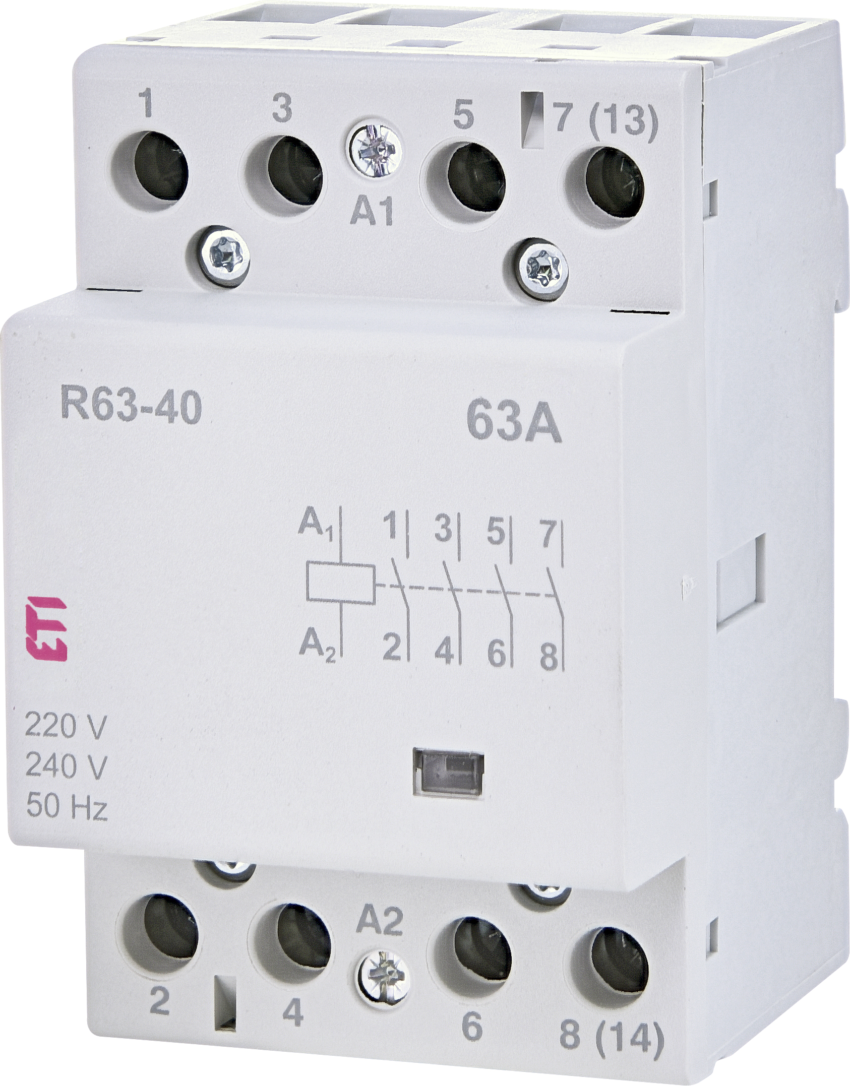
Timer And Contactor R Relay Diagram - Motor Circuits And ... from www.etigroup.eu Wiring diagram for telemecanique lc1 contactor replacements by us breaker lr aux nc1d aux nc1d aux m control. Electrical relay diagram and p&id symbols. 6 adjustable timer with relay. Time delay after coil normally open normally closed normally open normally closed relay, etc. Each relay activation will cause the light to toggle. Types, working and difference between them. Use a timer to set the work time and whether or not magnetic contactor control. Unique wiring diagram ac split daikin inverter well pump electrical wiring diagram irrigation pumps
C1, c2, c3 = contatcors (for power & control diagram) o/l = over load relay timers were used in many applications in our day to day life.one can see the timers in washing machines,micro ovens etc.
It is an electrical component used in a circuit with a lower voltage or a smaller current to switch on or off a circuit with a higher voltage and larger current. Wiring diagram for telemecanique lc1 contactor replacements by us breaker lr aux nc1d aux nc1d aux m control. Timer and contactor r relay diagram : Engineering electrical diagram contactor and timer. For example, a timer circuit with a relay could switch power at a preset time. Switching two relays at one time is like flipping 2 switches at once….with the same result. Each relay activation will cause the light to toggle. Electrical relay diagram and p&id symbols. When designing circuits using time delay relays, questions such as what initiates a time delay relay, does the timing start with the application or release of voltage, when is the output relay energized, etc., must be asked. Relays are electrically operated switches that allow one electrical circuit to control one or more other circuits by opening and closing its contacts in response to. Their purpose is to control an event based on time. Electronic timers, reversing contactor modules, and more. Ladder diagram or electrical schematic or elementary diagram can be divided into two.